DESIGN VERIFICATION
Design Verification
Both sheets of the schematic are now drawn, and it is always a good idea to spend a little time checking what we have before we move through to PCB layout. Proteus gives us two rather different ways to do that: the Electrical Rules Check, which is a formal report on the connectivity, and the Design Explorer, which lets us walk the design and see what we have actually drawn. We shall use both, and then look at what the AI assistant can add on top. In each case we introduce the tool and cover some basic functionality here; we do recommend that you read the corresponding chapter of the reference manual and spend some time familiarising yourself with the full set of capabilities.
This is also the point at which we promised to hand you a finished drawing. If you do not have a completed schematic, or would simply rather work from ours for the rest of the tutorial, load it now with the Open Sample command on the Proteus home page; the project is dsPIC33_REC_schematic.pdsprj under the tutorials category. Everything from here to the end of the tutorial works equally well with either design.
Note that what you see in the Design Explorer throughout this section will depend on whether you have drawn the schematic yourself or loaded the pre-supplied one from disk.
Electrical Rules Check
The Electrical Rules Check is the quickest check available and it is worth running before anything else. Invoke the Electrical Rules Check command on the Tools menu: Proteus compiles the netlist, examines the pin types connected to each net and presents a report in the Text Viewer, from where it can be saved or printed as required.
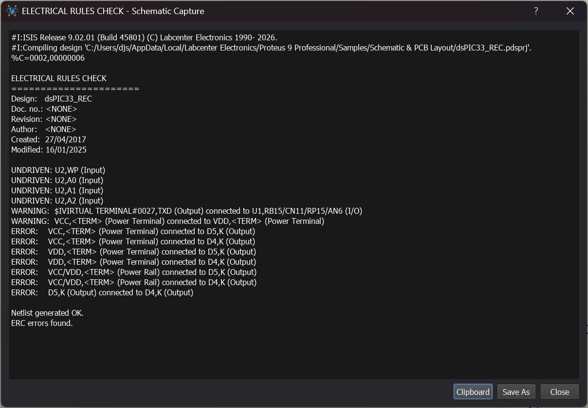
The Electrical Rules Check report for the data recorder displayed in the Text Viewer.
The check looks for two kinds of problem. The first is contention: two outputs wired together, trying to drive the net in different directions. The second is a net with no driving source at all, which is reported as an UNDRIVEN error. Terminals are regarded as having an electrical type for this purpose, so an input terminal connected to an input pin does provide that pin with a driving source.
Run it on the data recorder now. Bear in mind when you read the report that not every entry is necessarily a mistake, since an input pin may quite deliberately have been left unconnected, and that the more subtle errors will not be caught at all: the check knows nothing about part values, so a 10k where you meant 100k will sail straight through. What it does find is the silly wiring mistake, and it finds it early, which is exactly where you want it found.
See Also:
Electrical Rules Check (Reference Manual)
The Design Explorer
The Design Explorer can be launched from top level application module toolbar and will appear as a separate tab inside the Proteus application.

The Design Explorer icon
It is worth mentioning that, in terms of your Proteus workspace, you can detach tabs into separate frames. This is particularly useful if you want to view more than one module at the same time and have two monitors or a lot of space on screen. To split a tab onto it's own frame simply drag and drop it onto an area of free space. This will allow you to view both the Design Explorer and the Schematic at the same time.
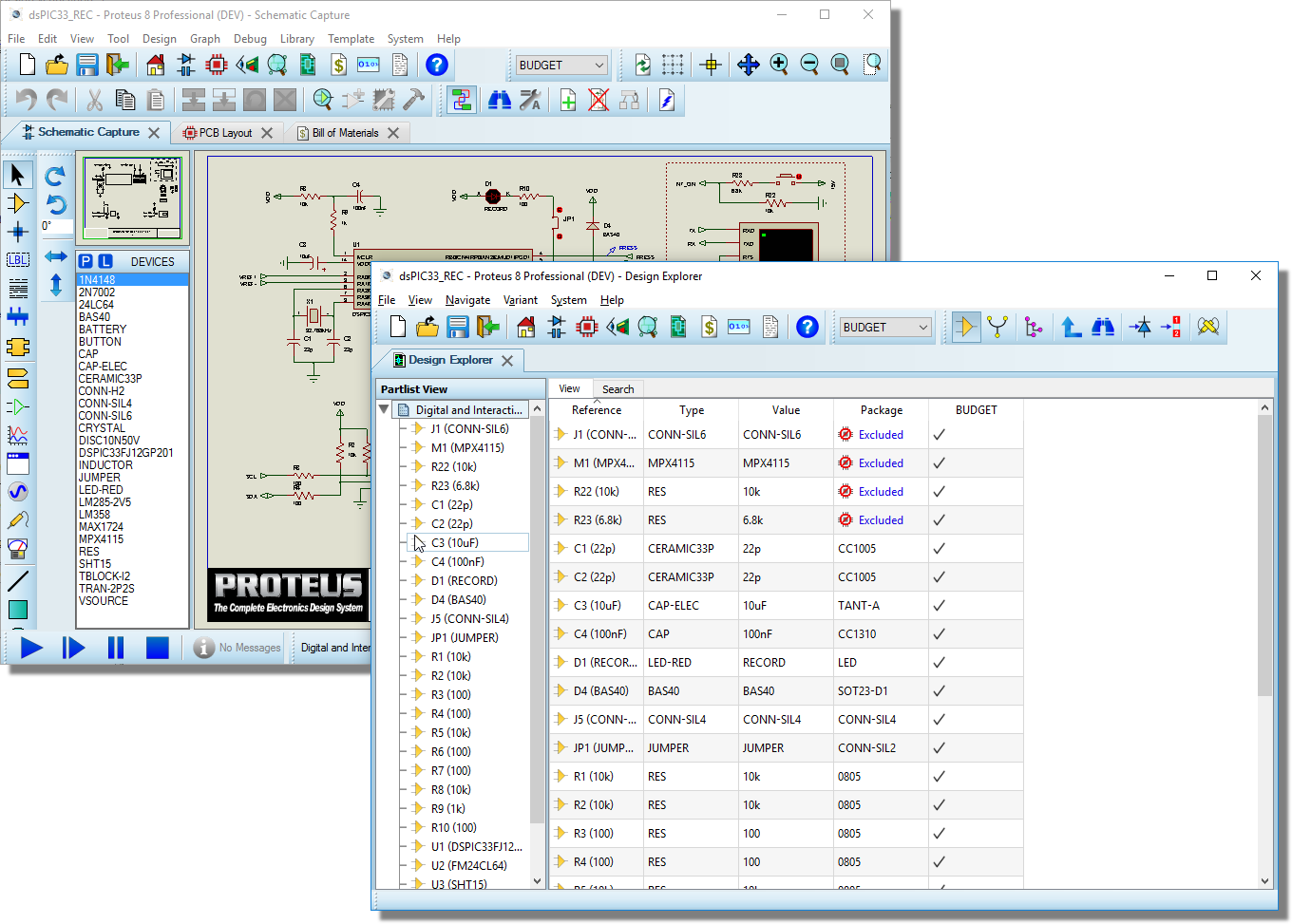
Split programs in Proteus
Alternatively, if you do prefer to work with tabs in a single frame you can quickly cycle between tabs using the standard Windows CTRL+TAB keyboard shortcut.
Once launched and in it’s default mode, you should see a dialogue form that looks a little like Windows Explorer. The left hand pane displays the sheets and the right hand pane displays the contents of the currently selected sheet. Clicking on another sheet in the left hand pane will force the right hand pane to show the contents of that sheet selected.
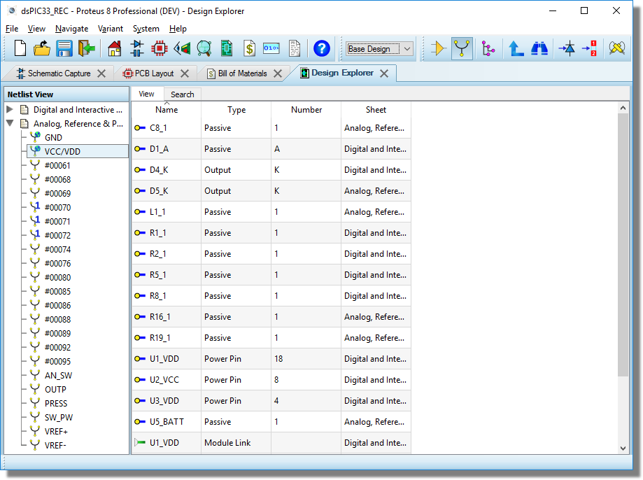
The Design Explorer
The Design Explorer has two distinct modes; partslist mode and netlist mode. The former will show a physical representation of the sheets (the components on a sheet) whilst the latter will show how the design is organised into groups of connections (nets). You can switch between the two modes via the Design Explorer Icons.

Design Explorer icon bar
Since we are in partslist mode by default let’s look at what we can do from there. The footprint used by a part is simply one of its properties, so it can always be checked one component at a time by editing that component; we shall do exactly that in the next section when we prepare for PCB layout. The Design Explorer shows us the bigger picture and allows us to make a global check of the packagings on the design at a glance. All of the footprints used are displayed beside their schematic reference at the far right hand side of the right hand pane so all we need to do is scan down the list to make sure everything is packaged, switch sheets (via the left hand pane) and repeat the process. If a part on the schematic did not have a footprint assigned it would have bright red text stating 'MISSING' in this field to highlight the potential problem.
A quick scan will immediately show that we do not have a packaging associated with the LED schematic part. Right click on the Design Explorer on the line with the LED and select Show Schematic Part from the context menu
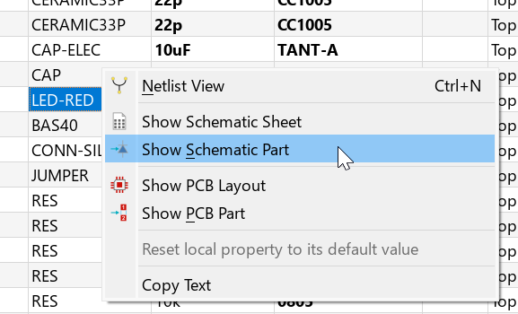
The Design Explorer's context menu
This will zoom the schematic around the part and tag it for editing. Simply right click on the highlighted part and select Edit Properties in the normal way. In the next section we shall look at how to browse the package library for a suitable footprint, but in this case take it as a given that it is named LED and simply type in LED in the PCB Package field of the dialogue form.
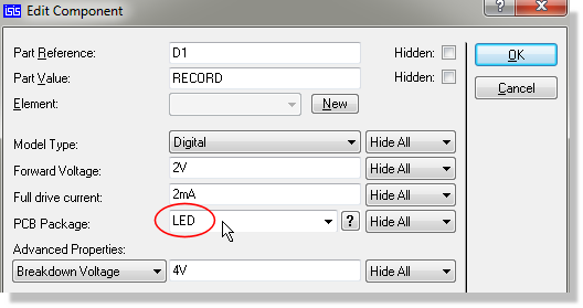
LED Assigned as the package
After making the change, the Design Explorer will live update to reflect the current status of the schematic.

Design Explorer showing the LED packaged
Now, simply follow the same procedure as above to change the footprint to an 0805.
We can also use the Design Explorer to investigate the connectivity of the schematic – for this we need to switch into netlist mode via the icon at the top left of the dialogue form. This will give us a view as shown below.

The Netlist icon
The first point to note is the net names. As we saw when we labelled the terminals, a net that includes a named terminal takes its name from that terminal; a net made up only of wire connections is simply assigned a number instead. We can right click on any net to view it’s connections on the current sheet by selecting the ‘Goto Schematic Net’ option from the resulting context menu. This is particularly useful when we want to check single pin nets for example, or if we want to name a net manually, which is covered in the section on connectivity considerations in the next chapter. Finally, where we have a net or nets grouped with a named net class (far right column on the right hand pane) it can be useful to check our assignments.
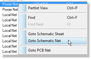
Goto Schematic Net will highlight the selected net
The Design Explorer is an extremely powerful tool and has many different uses throughout the lifecycle of a typical project. In particular it can be used as a link between the schematic and the PCB, facilitating cross-probing and PCB lookup. It has a manual of its own and we recommend that you read and work through it for more information.
See Also
Design Explorer (Reference Manual).
Checking with the AI Assistant
The Electrical Rules Check and the Design Explorer between them tell us a great deal about the connectivity, but neither of them has any idea what the circuit is supposed to do. If you have configured the AI assistant, ProPilot can offer a third kind of check: an informal review by something that has read the schematic and has some notion of what a data recorder ought to look like.
Bring the schematic capture tab to the front, open the chat side bar with the ProPilot (AI Assistant) command on the Help menu, and ask for the checks you want. Requests along these lines suit this design well:
- Check for unconnected inputs or floating pins.
- List any components without a power connection.
- Verify that the terminals on sheet 1 match the terminals on sheet 2.
That last one is worth its weight on this design. Connectivity between our two sheets rests entirely on terminal names matching, and a single typo in a terminal label produces two half-connected nets rather than one whole one. It is a mistake that neither the rules check nor a visual scan reliably catches, because both sheets look perfectly reasonable on their own.
Component references in the reply are returned as hyperlinks, so you can click any part ProPilot mentions and Proteus will jump to it on the schematic and highlight it.
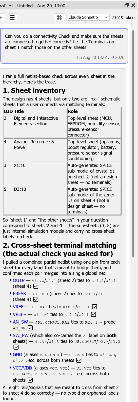
ProPilot reporting the results of an unconnected pin check on the data recorder, with hyperlinked Net references.
Phrase these requests as instructions rather than as questions. Asking "are my ICs all powered?" invites a yes or no answer and can produce a false pass even when something is genuinely wrong; "check that all my ICs have valid power and ground connections" pushes the assistant into actually tracing the connections. Use verbs like check, verify, confirm, list and highlight. Remember too that this is an informal review and not a formal rules check: use it alongside the Electrical Rules Check, not instead of it.
See Also:
Schematic Design Assistance (Reference Manual)
Usage Guidelines : Practical Guidance (Reference Manual)
Assembly Variants
Assembly Variants provide a simple method of managing multiple product configurations in a single schematic/pcb project. This is done by specifying the fitted or not fitted status of each component on a per variant basis. They are often used for excluding parts from cheaper versions of a product or for identifying PCB versions to firmware by controlling the use of pullup resistors on an MCU port.
In Proteus, Assembly Variants are configured primarily through the Design Explorer. Let's look at a simple example and we'll remove the SHT15 temperature and humidity sensor from a new product variant. Start by creating the new variant from inside the Design Explorer and naming it budget.
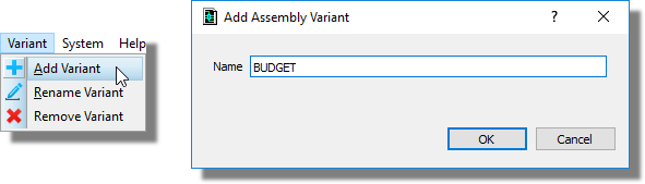
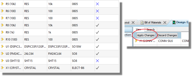
Notice that this gives us a new column in the component grid. Each entry currently has a tick which indicates that the part is fitted on the board for the variant. If we click on the entries for the budget column on U3 along with R5, R6 and R7 they will change to a cross. Clicking on the apply changes button at the top will then set these parts to be excluded from the BUDGET variant.
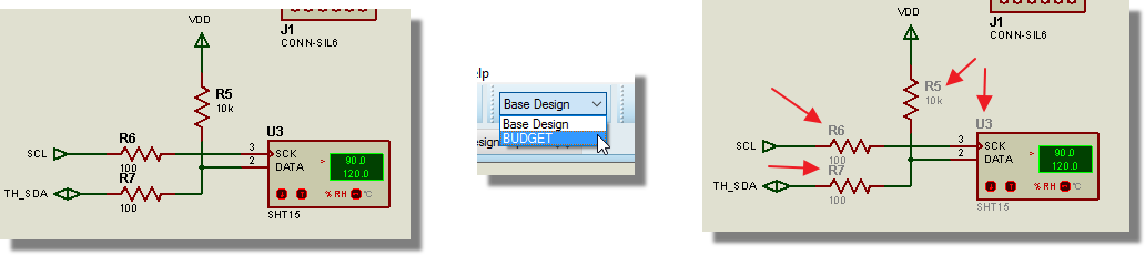
When you have more than one variant on the schematic you can switch between Active Variants via the variant combo box at the top of the screen. When we switch to budget variant you should see that the part references for the humidity sensor circuitry will be greyed out to indicate that those parts are not present in the active variant.
We could also have done this by individually editing the parts and checking the exclude from Active Variant box on the Edit component dialogue. You need to be very careful when working this way to ensure that you have first selected the variant you want from the combo-box at the top.

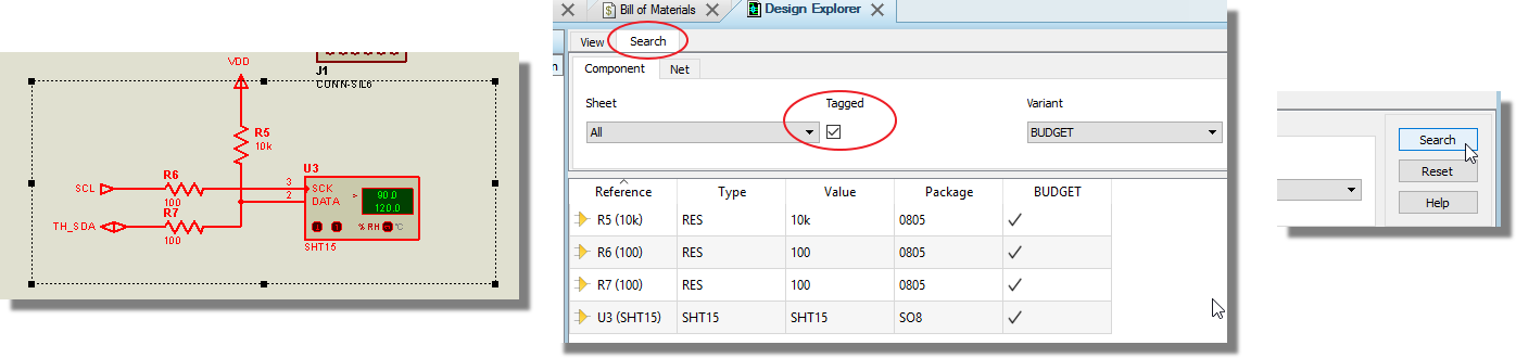
Finally, you can quickly manage variants for a group of parts by first dragging a selection box around the parts and then showing selected in the search tab of the design explorer.
The Proteus software manages the variant information through all of the output systems, changing the BOM Report, the Pick and Place files, the Assembly Drawings, the 3D Viewer and any export for MCAD to reflect the fitted status of the parts. Assembly variants do not affect the 2D PCB layout.
You can add the @VARIANT text string to the schematic to indicate the current variant on the schematic. This is a useful reminder and particularly important for printing schematic documentation. See the header block in the schematic reference manual for more information.
Assembly variants have more to them than we have room for here, and this is a good illustration of the other thing the AI assistant is useful for. If you have it configured, ask ProPilot "how do I use assembly variants in Proteus for multiple product versions?" and it will search a help database built for Proteus users and pull the answer together for you. Include the words "in Proteus" in any documentation question, otherwise the model is liable to answer with generic advice about EDA tools in general rather than about the software in front of you.
See Also: